Miracast – Wireless display/screen

While Google ChromeCast and products like Xiaomi Mi TV Stick supports wireless screen-sharing  and wireless streaming, they come with a caveat that may not make them the best solution in all cases

They require:

  • An mobile app to control them
  • A google account to use them

Especially the google account makes it a no-go for me.

However, if all you want it to stream Netflix etc., both these products might be a better option for you.

But if all you are interested in is a wireless screen for your pc or mobile device, there are other, simpler options

Continue reading “Miracast – Wireless display/screen”

Looking inside a Hue E27 bulb

I just stumbled upon this site, where fred27 have disassembled a White E27 bulb.

Part of his findings (everything below is his):

Onboard you’ll find the largest IC is a SAM21R21E18A. This is a nice 32-bit ARM microcontroller with built-in Zigbee. It’s the brains and communications for the device.

There are a number of test point accessible on the underside of the PCB. It took a fair bit of following traces, checking continuity with a multimeter and probing with an oscilloscope, but I managed to work out what many of these were for. This is what I found:

TP1 – Ground
TP2 – SWCLK
TP3 – SWDIO
TP4 – Serial TX
TP5 – Serial RX
TP6 – LED output (about 32V)
TP7 – Regulated 3.3V power to microcontroller
TP8 – RESET
TP11 – Ground
TP25 – power supply to LM2204 regulator

So there a number of interesting signal here. TP1 and TP11 are the signal ground for the microcontroller and logic circuitry. TP7 is the regulated supply voltage.

SWCLK (TP2), SWDIO (TP3) and RESET (TP8) are interesting. You’d need these if you want to load new firmware onto the microcontroller or debug it. Interesting stuff, but this is arguably starting to head over the ethical line of hacking. It’s more complicated than we need anyway.

The serial port (TP4 and TP5) are also interesting. You see some debug output on TP4 as the device powers up. Nothing as you use the device and switch the bulb on and off so not much use to us. Once again, more complicated than we need. If you want to take a look, it’s 3.3V TTL 115200 8N1.

I told you it was possible to play around with the device safely, and it is. NEVER power your device from the mains whilst poking around. If you have a clean 3.3V supply you can connect that to TP7 and power the device that way. Better still is to supply a slightly higher voltage to TP25. It’s usually at about 24V but even 5V (e.g. from a USB charger) will do the job. You might not be able to light up the LED board but it will connect to you Hue hub. At this voltage but you will be able to look at signals, but most importantly you’ll be able to do it safely.

Setting up a Hue Tap Switch

Update 2019-12-08: While the bridge until now has ignored all attempts from me to pair the Tap Switch, it suddenly changed its opinion after it was restarted recently.

After the restart, the bridge paired with the Tap Switch immediately (empty POST to /sensors, press button on Tap Switch according to Zigbee-channel for 10+ seconds while monitoring pairing via GETs to /sensors/new)

The bridge detected the Tap

{
 "8": {
 "name": "Hue tap switch 1"
 },
 "lastscan": "2019-12-08T12:01:29"
}

and added this config to /sensors

{
 "state": {
 "buttonevent": null,
 "lastupdated": "none"
 },
 "config": {
 "on": true
 },
 "name": "Hue tap switch 1",
 "type": "ZGPSwitch",
 "modelid": "ZGPSWITCH",
 "manufacturername": "Philips",
 "uniqueid": "00:00:00:00:00:45:xx:xx-xx"
}

After it was added, it detected the first buttonpress without issues (event 34), but since then absolutely NO buttonpresses on the Tap switch have been registered on the bridge. No idea why.

I have tried pressing hard and softer (always click’ing), long and doubled – all to no effect.


Original pairing instructions

I tried to follow instructions from here

Reddit

Following instructions, holding button down for 10+ seconds, then click again to “verify the switch works” and nothing happens.

On this video, it works

Which button to hold depends on your ZigBee channel:

  • ZigBee channel: 11 = button 1
  • ZigBee channel: 15 = button 2
  • ZigBee channel: 20 = button 3
  • ZigBee channel: 25 = button 4

Any device has to initially be within 1 metre of the bridge to first pair it.

and from here

Reddit
Button 3 depressed for 10 seconds puts them in pairing mode.
The TAP switch doesn’t need to be reset, it is using Zigbee Green Power protocol and to reconnect it with another Hue bridge you just have to follow the commision instuctions in the Hue app to pair it with another Hue bridge……

It cannot connect directly to Smart Things Hub, because that one doesn’t support Zigbee Green Power protocol (yet?).


9to5mac
Cnet
huetips


Dissecting the Hue Tap Switch


No constant connection and some Zigbee discussions


https://huetips.com/tutorials/how-to-add-a-hue-tap/#b57845a1eb852f4b2

Press and hold for 10 seconds the button it tells you to on the screen. The button will be different every time you connect a new Hue Tap. Make sure you press down hard enough to where the Tap makes a click sound.

The hue tap uses a zigbee transmitter like your bulbs, make sure you are within a few feet of your bridge and are pressing down the button all the way until it clicks and hold it for 10 or 12 seconds.


Philips Hue – Simple Control page

I have been looking for a simple control-page for Philips Hue lights for several reasons. I really do not like the app and not the least that you are only able to control the Hue lights from the two main “smart”phone brands. Secondly, if you want a control-panel in the livingroom, you primarily want the simple actions – turn on and off with an immediately recognizable functionality.

Inspired by this work, the download is sadly not available any more.

I have made a similar page, which can be downloaded here.

Inside the .html file, you only have to modify these two lines

 bridge='10.0.0.1' // Set ip-address or DNS name of your Hue bridge 
 hash='Hue user-hash' // Set the username-hash which is registered on the Hue Bridge

To use it, you can either run it directly for your own pc, or place it on a server inside your own network.

Controlling non-reachable Philips Hue Lights

Like so many others, I am from time to time affected by my lights going non-reachable.

Even when the light is “reachable”: false, the light is surprisingly still controllable by the hue bridge (if you specifically ask the bridge to eg. turn the light on via the Hue API)

It is somewhat strange, how the bridge can do that, if it thinks that the light is not reachable. It is of course possible, that it just send the command in the blind.

But what sadly does not work, are the rules and the schedules, which only (seem to) work on “reachable”: true lights.

I have not found any way to make rules work on non-reachable lights, but schedules works just fine, if you just add the light to a group, and make the schedule operate on the group in stead.

For instance:
Make a group:

{
  "lights": [
    "9"
  ],
  "name": "SpecialLights",
  "type": "LightGroup"
}

the group were created with id “5”

Make a schedule on the group:

{
  "name": "SpecialLight-On-18",
  "description": "SpecialLight on around 18",
  "command": {
    "address": "/api/<apikey>/groups/5/action",
    "body": {
      "on": true
    },
    "method": "PUT"
  },
  "localtime": "W127/T18:01:00A00:16:00"
}

Now the schedules work just fine – even when the light is “reachable”: false

[srs_total_visitors]

Add Hue lights by serial no

It can be a pain to add new devices to Philips Hue – it takes quite some time and sometimes, it does not seem to want to work – even with “touchlink”.

Anyhow, it is always nice to have an alternative, and in the Hue app, you can also add devices by serial-number. But how does this work with the Hue API?.

This Reddit page suggest you can add lights using the Hue API by sending

{“deviceid”:[“SN”,”SN”,”SN”,”SN”,”SN”,”SN”,”SN”,”SN”,”SN”,”SN”]}

with most likely PUT (but it may be POST)

it is not clear, which object the json should be PUT to


This page says that you can POST this Json
{“deviceid”: “light_id”}
(…where light_id is the serial number printed on the side of the Hue bulb.) to this object
/api/[hash]/lights


drashsmith.com


After a little trial-and-error, I get an error if I try to either PUT or POST on the root object (ie http://[ip-address]/api/[username]) saying that neither PUT nor POST were accessible on this object.
PUT was also not accessible on the “lights” object, but when trying to POST “{“deviceid”:[“SN1″,”SN2″]}” to the lights object (http://[ip-address]/api/[username]/lights), I got this reply

[
{
“error”: {
“type”: 7,
“address”: “/lights/deviceid”,
“description”: “invalid value, SN1, for parameter, deviceid”
}
}
]

which seems to suggest, that the serials for new devices should be POST’ed to the “lights” object. When I try to post the same Json to the “sensors” object, I get the same error, but I am not sure, that you can use the same method for the “sensors” object – I cannot seem to find serials on my sensors.

Happy hunting.

[srs_total_visitors]

Firmware extraction

Just found this site which discusses methods to extract firmware.

ianhowson.com

Could be interesting to try it out on a Maginon socket, but the relevant chip seem to be located on the backside and is thus not accessible without destroying a plug

Maginon SP-2 plug
Maginon SP-2 plug

If one is able to download the firmware from the supplier, it is much
easier

Reset cartridge status on Brother HL-4040 and similar

This tip can be found many places. I just copied it here for safekeeping

frightanic.com

My rather new Brother started raising “false” alerts (at least I think they’re false…) about empty/dead toner, “Toner Life End” it said on the device display. I had only printed a few hundred pages so far. In search for an answer Google directed me to http://www.fixyourownprinter.com/forums/laser/39806.

It’s a long and chaotic thread but about 1/5 from the top there is a posting that advises to do following for Brother HL-4040 and similar models.

How to reset toner warning “Toner Life End”

For the toner life reset menu:
1 Open the front cover of the printer
2 press and hold the cancel button
3 press the reprint button while still holding cancel
– here is the reset menu – go to the appropriate cartridge on
– the menu and reset it and you’re done!
– It seem to work the easiest, if you do it quickly

FYI… Pressing the “Go” button and the up arrow gives you the parts life reset menu (drum, laser, fuser, etc.)

I also did the electric tape over the windows – which worked before the reset – but I thought this fact would be helpful too.

For anyone that is asking “what window?” I think it is the clear plastic opening on the sides of the cartridges where you can actually see the powder inside the cartridge – the color of the toner (magenta, yellow, or cyan). I didn’t really know that for sure when I tried, but it made sense, and it worked. So I am fairly sure that is the “window” you should be trying to cover.

Comment from “Jezza P”

NB – every cartridge is listed twice on the reset menu “-H” for High capacity cartidges and “-S” for standard – make sure you pick the correct one for your cartidges otherwise it errors. 130 are standard and 135 are high.

Maginon SP-2 Smart Plug – Final part

The only thing that remains is to create the code to make the initial setup and some code to turn the plug on and off.

Although I have been a software developer for many years, I have never really made much socket-programming, so I tried to find something on the internet to build on.

After quite some searching, I found this discussion on stackoverflow.

This actually issues the correct commands to make the initial setup of a Maginon SP-2 smart plug. However, it needs a small correction to make it work with the Maginon plug – the same that I mentioned earlier with regards to the Orvibo socket. Alle replies from the socket will be received on UDP port 48899.

I have made a corrected version of the register.c program here.

Before you compile the program, change these two lines to match the SSID and Wifi password to your own router  (change DLINK to your SSID and the xxxPASS_WPA_PASSxxx to your Wifi password.

static const char *ssid = "AT+WSSSID=DLINK\r";
static const char *sec_settings = "AT+WSKEY=WPA2PSK,TKIP,xxxPASS_WPA_PASSxxx\r";

The program is compiled with:

gcc -O0 -o register register.c

Before you run the program, be sure to assign the socket a static ip-address in your router. To do this, you need to get the MAC address of the socket, and then in your router, assign a static ip-address to that MAC address.

Now run the program

register

When the socket reboots, it should connect to you own WIFI router. Check the router to see if it has done so.

When it is connected, these two python scripts to turn the socket

On:

#!/usr/bin/env python

from socket import *
from datetime import datetime

HOST = 'plug1'
PORT = 8899
BUFSIZ = 1024
ADDR = (HOST, PORT)

tcpCliSock = socket(AF_INET, SOCK_STREAM)
tcpCliSock.connect(ADDR)

data2 = 'AT+YZSWITCH=1,ON,'+datetime.now().strftime('%Y%m%d%H%M')
tcpCliSock.send(data2)
data1 = tcpCliSock.recv(BUFSIZ)
print data1

tcpCliSock.close()

and Off:

#!/usr/bin/env python

from socket import *
from datetime import datetime

HOST = 'plug1'
PORT = 8899
BUFSIZ = 1024
ADDR = (HOST, PORT)

tcpCliSock = socket(AF_INET, SOCK_STREAM)
tcpCliSock.connect(ADDR)
data2 = 'AT+YZSWITCH=1,OFF,'+datetime.now().strftime('%Y%m%d%H%M')
tcpCliSock.send(data2)
data1 = tcpCliSock.recv(BUFSIZ)
print data1
tcpCliSock.close()

In both cases, you should modify the HOST line in both scripts and set it to the DNS name or the ip-adress of your plug

When you can turn the socket on and off, you can also try to use the delay command

AT+YZDELAY=1,OFF,5,201701232127

It can be used for both ON and OFF. The number after ON/OFF is the delay in minutes.
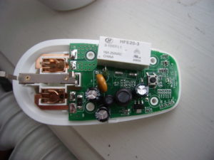
Maginon SP-2 Smart Plug – Part 3

Go to part 2

Since the investigation until now has not given any concrete hints as to how to achieve the main goals:

  1. Make the socket associate and connect to my own Wifi network
  2. Make the socket turn on and off

another approach was needed.

The next most obvious option to me, was to try to intercept the network-communication between the Maginon SP-2 app and a WIFI network. To do this, the app has to believe that it is connecting to a real socket. So I set a router up to imitate the Maginon socket – with the same SSID and WPA password that the socket uses. The router did not allow for modifying its MAC-address.

Sadly, although I, a few brief times, was able to see my “fake” WIFI from the app, I was never able to make the app believe it was the real socket enough to make it try to associate with it. This was a bommer, since I have read about several other sockets, where this was trivially easy. I still do not know why the app did not believe it was a real sockets WIFI.

Next option – decompile the Android app and look for hints. There are several free sites which will decompile an APK file.

With the Maginon app decompiled, you can search for a lot of interesting things in the .java files (eg. using ‘find’ in Linux or something like WinGrep on Windows)

  • 48899
  • 8899
  • http:
  • HttpGet
  • AT+
  • AT
  • 10.100.100.254
  • 192.
  • Reco
  • connect
  • admin

When you look into the java-files that contains these search-words, you learn primarily three things:

  • A list of URLs that the app accesses. This is the final “proof” that the socket is probably a Reco4life socket
  • A suggestion, that port 48899 is used to set up the socket and port 8899 is used for ordinary use afterwards
  • A list of AT- or AT-like commands that the app issues to the socket
Port AT command Description
8899 AT+YZSWITCH=1,ON,201410292146\r\n Switches the socket on
8899 AT+YZSWITCH=1,OFF,201410292146\r\n Switches the socket off
8899 AT+YZDELAY=1,OFF,5,201410292146\r\n Switches the socket on or off after a delay (in minutes)
8899 AT+YZOUT\r\n Seems to return the energy consumption statistics
8899 AT+VER\r\n Returns the version of the socket SW and (probably) the Wifi stack SW
48899 AT+EPHY=off\n  Disable ETH interface
48899 AT+FAPSTA=on\n
48899 AT+LANN\n Query LAN setting in AP mode
48899 AT+PING=173.194.72.103\n PING ip address
48899 AT+PING=176.58.117.69\n PING ip address
48899 AT+PLANG\n
48899 AT+Q\n
48899 AT+WANN\n Query WAN setting in STA mode
48899 AT+WMODE=APSTA\n Set WIFI work mode
48899 AT+WMODE\n Query WIFI work mode
48899 AT+WMODE=STA\n Set WIFI work mode
48899 AT+WSKEY\n Query WIFI Security parameters as STA
48899 AT+WSKEY=OPEN,NONE\n Set WIFI Security parameters to no encryption
48899 AT+WSKEY=pwMethod,PwMatch,Pwd\n Set WIFI Security parameters
48899 AT+WSLK\n Query WIFI link status as STA
48899 AT+WSSSID=ssid\n Set WIFI target AP SSID as STA
48899 AT+Z\n Restart WIFI module
48899 HF-A11ASSISTHREAD Sending command to the socket will make the socket respond with its ip-address etc. If you respond with “+ok” all the other AT-commands are enabled for use. Some sites call this command as a sort of “password”.
48899 WIFIKIT-214028-READ Unknown
48899 YZ-RECOSCAN Sending command to broadcast address will make all sockets in network respond with their ip-addres, MAC and hostname
48899 +ok Response to HF-A11ASSISTHREAD

“\r\n” means CRLF (characters hex 0a + hex 0d)

3 of these commands stand out

  • HF-A11ASSISTHREAD
  • WIFIKIT-214028-READ
  • YZ-RECOSCAN

From the .java files, it is clear that YZ-RECOSCAN is used to scan a network for active sockets. The purpose of WIFIKIT-214028-READ is not clear from the sources, and a search on Google does not turn up much usable.

HF-A11ASSISTHREAD is another matter. The usage in the .java is not clear, but a search on the internet brings up a lot of interesting links.

One of them is this post from Andrius Stikonas concerning an Orvibo S20 socket. The control part of this socket is clearly different from the Maginon socket, but the setup/initial pairing-part seems to be similar. Strangely enough, the description from Andrius cannot be used 100% for the Maginon socket. Andrius writes, that “The socket always replies to the same port as the source port of your message.“. This is not correct in regards to the Maginon socket which will ALWAYS respond back to your source ip on UDP port 48899. Hence, in your code, you need to control both source and destination UDP port. Apart from this, the description from Andrius can be used directly for initial pairing of the Maginon socket.

Now we have the needed information to setup and control the socket.